
UHJ And B
Format Ambisonic Decoder
Advertisement: If you're
enjoying these pages and you have an interest in hobby
type electronics or repair jobs, you might like to visit
my UsefulComponents Etsy Shop where there are many difficult to find items,
and my other website www.usefulcomponents.com,
where there are details of some good radio and other kits.
1.0
Introduction
This document summarises the workings of a
surround sound decoder intended for use with Ambisonic B-format
and UHJ sources. The decoder is intended to be a reference
quality prototype with maximum flexibility for experimental use
with different speaker layouts. A new improved version has been
added at the end.
Special
notes added for Web Release
What's Ambisonics? If you've got this far you
probably already know, otherwise, you don't need me to show you
how to use a search engine. The University of York has a good
site on the subject. Just remember that while looking through
all the diagrams of polar patterns explaining M-S recording and
soundfield mics, that the front lobe signal is of opposite
polarity to the rear lobe, and the same applies for left
and right. Some form of + and - drawn hastily in crayon on these
diagrams would have saved me several days of head scratching.
Also worthy of note is that people use the word phase to
describe polarity when discussing B-format. OK,... I know that a
180 degree phase shift appears the same as inversion for a given
sine wave, but it can be confusing when discussing B-format and
then going onto UHJ; In UHJ a 90 degree phase shift is used and
things get literally more complex. B-format uses no awkward
phase shift filters so when people talk about phase shift in
B-format then they are talking about the special case of 180
degrees or inversion. This is part of the beauty of the system,
as signal inversion is easy to do while maintaining high
fidelity.
Since writing this I've added a
B-format volume control. I used to use the volume control on my
quadraphonic amp for room volume control. But when I built some
more speakers I realised that I would have a problem. Either I
would have to put a well matched volume control in the Stereo
UHJ input or make a B-format (i.e. triple gang) volume control.
As I knew that I'd be playing with B-format sources eventually I
opted for doing the job right, and started looking for triple or
quad gang volume controls. As is often the case with tricky to
source items, they are available from the pot manufacturers
direct in large quantity, but not from the usual catalogues. So
I decided to use a triple gang 12-position switch and use
resistors to make 3dB steps, plus a mute position. This I
installed in the B-format feed and it was fine. There is a
different way to do it that I've found since though, which could
be much nicer. A brief description follows;
In a non-inverting op-amp feedback circuit it is easy to use a
variable resistor to GND to create increasing gain with a
reducing resistance. And in a slightly different op-amp circuit
it is easy to have a resistor to GND create reducing gain with
reducing resistance. The cunning part is to use each end of one
single gang potentiometer connected in both of these circuits,
with the wiper grounded. So, as the wiper is grounded
there is no crosstalk between the circuits and as you move the
wiper from one end of the track to the other, the gain increases
or decreases in both circuits. It's clever, and as far
as my very sketchy thought about this circuit goes, should still
be fine with log pots, so it will be fine for audio weighted
controls. Using this system, a cheap double gang pot from
Farnell becomes a quad gang pot; Ideal for B format volume
control.
2. General Description
There are two main sections to the instrument.
The UHJ decoder board, amb02 accepts 'stereo' UHJ sources and
converts them to B format. The B format decoder board, amb01
generates the audio signals for each speaker from the B format
signal. This B format input signal can come either from the UHJ
decoder or from a separate B format source. The stereo UHJ
signal enters on two domestic phono sockets. The decoded B
format output is on a 5 pin male XLR which conforms to the pin
assignment used on the historic Audio and Design Ambisonic
units. The B format input to the B format decoder is a female
5-pin XLR. Finally, the outputs to the amplifiers are once more
on domestic phono sockets. The decoder deals only with
horizontal surround. The Z signal is ignored. The Texas TL074
quad op-amp is used extensively, as it is a good audio performer
while being cheap. Shelf filters are not included. Shelf
filtering alters the spectral content of the W signal relative
to the X and Y signals to compensate for the blocking effect
that the head has on the right ear when a sound comes from the
left direction. The degree of filtering is different for
different speaker layouts, making it difficult to apply in a
generalised decoder like this one. Phase distance compensation
is not included in this decoder either. Phase distance
compensation attempts to make the wavefronts more spherical in
some way by applying a phase equalisation at a very low
frequency. Once more I elected to omit this feature as it seemed
to be a very small finessing of the system, and again is
dependant on speaker layout. Amplitude distance compensation is
available for each speaker in steps of 2dB.
2.1. Schematic Description
PSU, Input Buffers, amb01-01.sch
This sheet shows the voltage regulators which
are standard. Approximately ±14V is chosen for the voltage rails
as this allows the use of a 12V transformer. There is about 4V
drop available to the regulators which lets them stay well out
of drop-out without dissipating too much power. The B format
input enters the board from the rear panel XLR onto a six pin
header. The W signal is buffered and amplified by root 2 at this
point so that it is at the correct level for simple equality
gain summing in later stages. X and Y are unity gain buffered
and inverted versions are created. This gives ±X and ±Y signals
for selection by the later switching stages. The X and Y signals
leave the sheet and have the appropriate SIN/COS weight and
polarity selected by the front panel switches. The signals
return on the same connectors and are summed on amb01-02.sch.
2.2.
Schematic Description Sine-cosine
Pots, Angle Select, amb01-02.sch
Editorial note: Halfway through building this
section of the the circuit it became clear that it could be
simplified considerably by changing the values of the
sine/cosine weighted resistors and removing the buffering amps
here. Also, a buffering stage could be removed from the distance
compensation circuits. However, in order to "get on with it,"
the design was built as shown.
The signals from the polarity and weight
selectors are buffered and then summed back in with the W signal
to create the feed for the loudspeakers. These feeds are
returned to the front panel where the distance compensation is
applied. This is simply a power weighted volume control with
discrete steps.
2.3. Schematic Description
Distance Compensation, amb01-03.sch
Note: As in the above circuit, a buffering
stage could be removed from the distance compensation circuits
as well. This could reduce the number of op-amps which the
signal has to travel through.
The returns from the distance compensation are
buffered again before being sent to the rear panel phono
sockets.
2.4. Schematic Description
amb01 Sector Selector
Wafer Switches wd01-01.sch
This is a wiring diagram rather than a schematic and shows the
wiring between the molex headers on the board and the front
panel switches. The first switch is a four position wafer switch
which is wired to apply different polarity versions of X and Y
to each end of the second switches. The second switches are dual
wafers and perform a sine/cosine weighted gain selection of the
selected X and Y signals. The first switches effectively select
which quadrant of the room the speaker is positioned in. The
second switches allow the speaker position to be selected within
that quadrant in 9° intervals. The use of switches here removes
the need for sine/cosine weighted pots and also gives a set of
highly repeatable settings. This is not as well controlled with
continuous rotation pots.
2.5. Schematic Description
UHJ Matrix, Phase Sequence Array
amb02-01.sch
The left and right stereo/UHJ signals enter the
instrument on domestic phono sockets and are connected to the
UHJ decoder board amb02 on a four-way header. Power is sourced
from board amb01. The input signals are first given a frequency
lift in the mid band as the frequency response of the phase
shift network is, unfortunately, not flat. The left and right
signals are then summed and differenced to form the required
sigma and delta signals. Note that a signal inversion occurs at
this point to produce -(L+R) for sigma and -(L-R) for delta, but
this has no significant effect. These two signals are buffered
and a polarity inverted version created. You could remove an
op-amp from this stage without loss of quality. The ±sigma and
±delta signals feed the two phase-sequence matrices which
generate four convenient quadrature outputs.
2.6.
Schematic Description W
Sub-Woofer Drive, Matrix Sum, Outputs amb02-02.sch
Four signals from the phase-sequence matrix are buffered with
high impedance buffers. These are S_0 S_90, D_0 and D_90. When
viewed on an oscilloscope, S_0 comes 90° before S_90 and so S_0
is used as the 90° phase advance signal described as j sigma in
my comments and in the decoding equations. The same applies to
D_0 and j delta. This gives us all the required signals to
perform the decoding equations with op-amp summing as shown.
Note that once more, the signals are effectively inverted here
as subtraction was more conveniently implemented as addition and
vice-versa. The effective decoding is not changed.
The reconstructed W', X' and Y' signals leave
the board on a header and exit the instrument on a 5 pin male
XLR.
An additional circuit has been added to the instrument to provide an output for a sub-woofer. This simply outputs the mono W signal and has an independent level control and another control to vary the cut-off frequency between about 30 and 200Hz. The filter is a flat, two-pole Butterworth.
3. Future
Designs
There are several things which can be improved
in this decoder design.
3.1. Op-Amp Minimalisation
As mentioned in the text, by altering the circuitry slightly
around the angle selection switches, one or more op-amps may be
removed from the signal chain to improve overall fidelity.
3.2. Pots And
Switches
To use the speaker amplitude balancing pots it is possible to
measure the distance from the listener to each speaker and
"dial-in" an accurate compensation on these rotary switches, but
this has problems.
1) The switches used for the distance compensation are not very
good for audio signals. The contacts and wipers are not gold
plated and poor audio connections have developed across these
switches used in another application after only a few months of
light usage. This can be very annoying in used, as channels cut
in and out at random and the switches need to be given a hearty
wiggle to get the contacts wiped and reconnected.
2) In practical use, the conditions in the room change the
perceived loudness of each speaker and the dial-in settings are
not the most suitable. I found that setting up the speaker
balance by playing back Ambisonic and stereo material gave
better results in a real room, so the accurate steps are not
needed. It would be an improvement and cost reduction to simply
replace these switches and resistors with plain old audio pots,
or not have them at all and to rely on level pots which are
usually available on whatever speaker amps are being used.
The quadrant and 9 degree angle controls are very awkward to use in practice. Having used the decoder, 9 degrees is far too fine a graduation to notice in practice and having to figure out which quadrant the speaker is in every time is clumsy and confusing, especially as the speaker can be correctly set in two different quadrant settings if directly at the font, back, left or right positions, using 0 or 90 degree angle settings. Confusing.
A better way to do this would be to use a 12 position switch to simply dial in the angle of the speaker in a more intuitive way, with the fully anticlockwise switch position being the directly rear 6 o'clock speaker position and fully clockwise being the slightly to the right rear 5 o'clock position. The switch can be a simple, cheap, 12 way switch which drives on-board electronic switches in the appropriate way to give the correct output. This will save on audio wiring to the front panel. A 12 way switch would be nice, as the positions of the clock would be a natural way to describe the angle of the speaker position. Also, the cheap 12-way rotary switches available have 30 degree steps and a 30 degree angle between the two end stop positions, and so perfectly indicate the actual speaker location on the front panel.
Removing this excess of knobs will allow a smaller rack case to be used.
3.3 Phase Shifter Circuits
These are variously referred to as Hilbert filters, 90 degree phase shift filters and more. The phase sequence array was the only practical way I could find of performing this function at the time of construction. The phase sequence array looks very decorative on the schematic, but I have to admit that there are better ways of doing this which don't particularly require any more precise components or suffer from any other special disadvantages. With the passage of time it has become clear that the dip in the frequency response in the mid-band is quite a major disadvantage, even when compensated for. A better way to achieve the same thing is shown in my ambisonic microphone UHJ encoder circuit, which is based on Jurgen Haible's phase shifter in his frequency shifter circuit, which in turn is based on a classic design by Mr. Bode himself in the Bode/Moog frequency shifter effect unit. In 1998, the time of original construction of this design, the internet was a smaller place and my attempts to get schematics for these superior circuits failed. Board amb02 will be replaced at some point with these improved circuits.
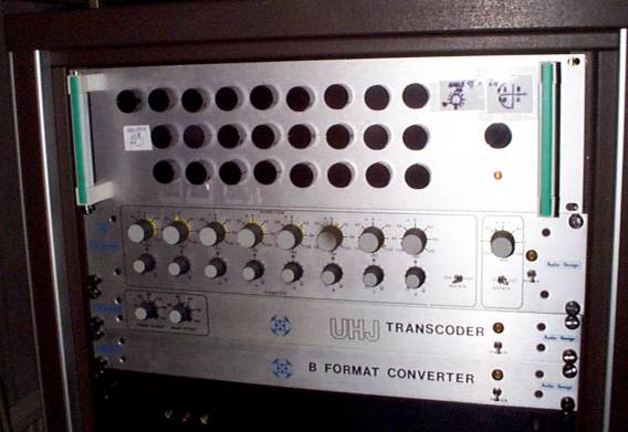
5 Pictures
UHJ Ambisonic Decoder Installed In the rack.
Next to the old, but reference standard Audio and Design Pan
Rotate unit, which along with the UHJ encoder is very useful for
testing any new decoder design. Getting mixed up on a signal
polarity, or even more so a 90 degree phase advance or retard is
very easy, as I found.
You can make a pan rotate unit much more easily using linear
joystick pots, as shown in my own analogue VCO controlled
pan-rotate design. The Audio and Design unit uses Sine-Cosine
double gang pots.
If any viewers have Ambisonic equipment for sale, please feel free to contact me for an informal chat.
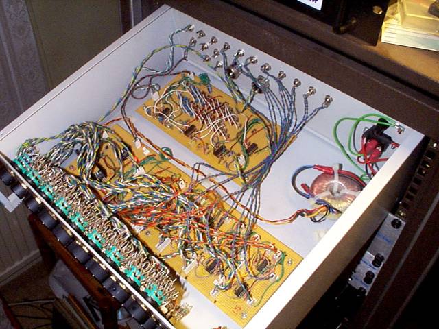
Phase Sqeuence Array Inside Ambisonic Decoder
You can see the regular phase sequence array towards the back, as also used on the pitch shifter. There's a lot of front panel resistor wiring.
Ambisonic Decoder Rear Panel, Shows B-Format Link And Speaker Feed Outputs

Amplifier Stack
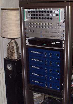
Here we have a stack of 5 Stageline STA-100 rack mounted amplifiers for driving the 8 speakers in the Ambisonic system. The choice of amplifier is worth discussing.
1) I wanted rack mounted amplifiers. I detest having hi-fi amps hanging around on shelves and falling off when some cable gets pulled from behind and the general hassle of the traditional messy separates stack. There comes a point where there is too much gear to manage like that.
2) Good quality budget Hi-fi amps may have been cheaper, and even sound better, but they tend to have tone controls. Even when set flat these controls add a significant phase shift which will vary slightly between amps and will vary greatly if you try to mix different types of amps. This is no good in a system which is trying to be phase coherent.
3) Rack mounted amps tend to have gain separate controls for each channel. This removes the restriction of having to control the gain in stereo amp pairs. This is very convenient when I'm sat at the PC which is more or less between the two rear speakers, and I can turn down the gain on amps 4 and 5 which are on separate units to compensate for my listening position.
4) The Stageline units are cheap for a rack mounted amplifier and fair quality, using as they do the National Semiconductor LM3886 Overture amplifier. Now, I know that this is an integrated power amplifier and as such can never offer ultimate Hi-Fi quality. But it can offer me a well defined level of quality as I can look it all up in the data sheet. They are also very resistant to incorrect drive or faulty speaker connection, and I can always buy new ICs if I manage to destroy them by some form of unfair abuse.
5) These amps have no noisy fans, just nice big heatsinks.
Looking at the booklet, the design looks German and the manufacture was done in India. In general, these are well-built amplifiers. I reverse engineered a schematic and found that, in my opinion it was actually rather over-engineered. There are two whole op-amp stages before the PA, just to buffer in and out of the gain control. This is just throwing money away in an amplifier that is clearly designed down to a price. Also the output had an expensive wirewound resistor in the RC output snubber circuit and a cheap low value resistor across the output inductor. To my mind, these are wrong way round and over-engineered. There were plenty of other things I fancied snipping out too, which would if anything improve the sound and not compromise the CE mark or the reliability. I did this on all five amps, removing the un-needed op-amp stages and multiple inter-stage electrolytic coupling components.
The bottom amp drives a sub woofer, or in fact a pair of big Arcam hi-fi speakers positioned on the floor under the settee with each driver facing outwards, driven in phase. Cut off frequency on the feed to these is set to about 80Hz on the Ambisonic decoder which generates the signal. I'd like to pretend that there's some really highly technical theory or measurement to this, but in practice I adjust the cut-off frequency and gain on this signal until it sounds about right in the room.
Other Notes:
I bought these amplifiers from an electronics importer, Electronics City Wholesale. The Stageline STA-100 was £105 each, and you get a small discount if you spend lots.They no longer stock this amplifier though.
I first tried the slightly higher power Skytec PA2100 amplifier, hoping that this would have a Nat Semi IC PA. It didn't, and was a diabolical amplifier, the designer of which should be given a firm slap. It has a cooling fan which is incredibly noisy. The cooling fan is 12V and is run though a resistor from the main d.c. supply, ending up with about 16V across it. This will fail quickly. Naughty!
The Skytec amp has MOSFETs on the output but I was a bit suspicious when I saw that there were no thermal sensing bias components on the heatsink. When I tried it, it sounded awful. The crossover distortion was clearly visible on my old oscilloscope, and the amp could clearly get nowhere near the distortion level claimed in the booklet. It went back to the shop who agreed to restock it at a reasonable charge. I wasn't wanting to bash the seller as he clearly ran on small margins and the amp was not defective as such, just a nasty, nasty design aimed at cloth-eared disco monkeys.
This will partly explain why so many awful clubs and discos you may have accidentally happened to be in sound absolutely dreadful. If you see a cheap looking, or Skytec branded rack mount amp behind a tinsel covered disco booth, the excess of high frequencies caused by the crossover distortion may be one factor contributing to your bleeding ears. I guess the moral of the story is that with cheap imported equipment, some is just fine and some is terrible. But then as the guy at the shop said, he'd sold plenty of them and had no complaints so far, the usual question being "how loud will it go?"
Ambisonic
"Clock" Decoder With Phase Shifted Crosstalk Cancellation
I have actually built this as of 30-SEP-2019
and use it when watching films. There are no listening
miracles to be had from the phase-shifted crosstalk cancellation
I'm afraid. It would still be nice to test it in a more
controlled environment.