Electrostatic Negative Air Ioniser With Rotating Ion Thrust Emitters
Advertisement: If you're enjoying these pages and you have an interest in hobby type electronics or repair jobs, you might like to visit my UsefulComponents Etsy Shop where there are many difficult to find items, and my other website www.usefulcomponents.com, where there are details of some good radio and other kits.
Safety Precautions
This EHT power source is very safe when constructed and boxed, as the output is current limited by the high output resistance. However you can get a nasty shock from the individual capacitors if you accidentally touch them while connected to the mains and for some time afterwards. Be sure to disconnect from the mains and discharge the device by shorting the current limited output to ground for some 10 seconds before handling the insides. I also recommend running a ground lead with a 100k Ohm resistor in line down the entire row of capacitors before touching. It is possible to use the EHT output to charge a high voltage external capacitor like a home made Leyden jar. This could produce a lethal high current shock, so don't try anything like that unless you really know what you're doing.
EHT Generator Circuit Design
Mains Driven EHT Supply for Negative Air Ioniser: mains_ioniser01-01.sch (pdf)
A basic mains driven Cockroft ladder high voltage generator is shown in the schematic. This is functionally the same as a project in Electronics Today International many years ago. The peak mains voltage of 340V appears across each capacitor and this is negative with respect to mains neutral and the surrounding environment. The orientation of the diodes defines the polarity. As the capacitors are in series, the voltages sum and at the top of the ladder about 7kV is present. A high value resistor is used at the output end to current limit the output. It is important to use a high voltage rated resistor or a string of lower voltage ones in series, so that the resistors maintain their stated resistance value. This design is for 220 to 240V mains power and a double length ladder would be needed for 110V supply. The ETI version used just 10nF capacitors. This version uses 47nF so could theoretically output 4.7 times the current. In practice this is limited by the output resistor stack. What you could do, though, is have two or more, maybe up to four outputs using separate resistor stacks connected to the top of the ladder and still keep the output voltage up for air ionisation purposes.
EHT Source Construction
The diodes and capacitors are simply wired together with solder using just the existing component leads.
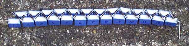
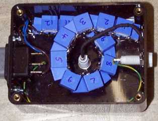
The ladder is put into a small plastic box and wired to the mains IEC inlet and the EHT output socket. After an initial test to make sure that the connections are correct, the box is filled with wax made from melting down household candles in a saucepan. This stops ionisation occuring inside the box which would otherwise reduce the available output. The output socket is an ordinary 4mm socket and a mains earth connection is also wired to an adjacent socket. A one Amp plug-top fuse is used in the mains lead.
Ion Emitters
If a single dressmaking pin or other sharp point is connected to the EHT output you will be able to feel a slight breeze of negatively charged air molecules coming from the end of the point. The high charge density at the sharp point causes this ionisation and the negative ions are then repelled from the negatively charged pin, causing this ion breeze. You can also hear the point emitting a slight hiss and in very dark conditions you can just see the point glow slightly. The ionisation at the point tends to physically degrade it over time and this reduces the ionisation occurring there. Some commercially available air ionisers have precision shaped points of special alloys to counter this. One fun way to make sure that your ioniser is still ionising is to use the ion breeze thrust from the needles to spin a rotating emitter pair.
Spinning Ion Emitters
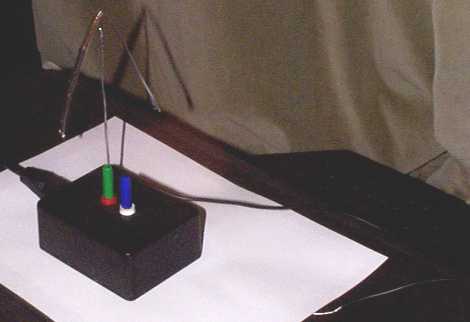
A12cm long piece of stout copper wire is soldered into a 4mm plug and this is plugged into the EHT output. The top end of the wire has an ordinary steel dressmaking pin soldered to it. This is the point on which the spinning emitter arrangement balances. A section of aluminium foil about 20 cm long and 6cm wide is folded multiple times down its length until it is about 20cm long and 0.5cm wide. This gives the foil more strength. Try not to leave any sharp edges or points as these may ionise the air in unwanted places on the structure. If you can find a thick aluminium foil pie-tin then this is better. You could just cut that to the desired width and there will be no need for the multiple folding. The head end of two pins are folded into each end of the foil strip pointing in opposite directions. Then the strip is folded in the middle so that it forms an inverted V shape. This can then be placed on top of the balance point. When the power is turned on the ion breeze will push the inverted V round and it will remain spinning as long as there is sufficient ionisation happening at the points. The spin speed can be increased by putting a sheet of aluminium foil connected by wire to the ground terminal underneath the whole arrangement. I put a white sheet of paper over this to collect the fine dust and smoke particles that the ionised air precipitates from the atmosphere.
I'm sure that this design can be changed and improved in myriad ways, but this experiment demonstrates that spinning your ioniser emitters under their own ion thrust is very easy. Maybe the spinning action encourages ion emission by moving the needles through relatively un-ionised air. Maybe you could aerofoil shape the structure to gently fan air up or down past the system. There are many possibilities, and the spinning emitter has great novelty value.
Edit 23rd February 2010:
I've had two of these running now for about
five years using standard pins and a graphite pencil lead as the
pivot. To keep them rotating you just have to wipe dust from the
emitter pins every few months or so. If you fancy making one one
of these, bearing in mind the safety precautions.